Vanton - Chem-Gard Horizontal Centrifugal Pumps - Chem-Gard CGM
Magnetically Driven, Sealless, Centrifugal Thermoplastic Pumps
meet ANSI B73.1 standards
- Flows to 400 gpm (91 m3/h)
- Heads to 180 ft (55 m)
- Temps to 225°F (107°C)
- Construction: PP, PVDF
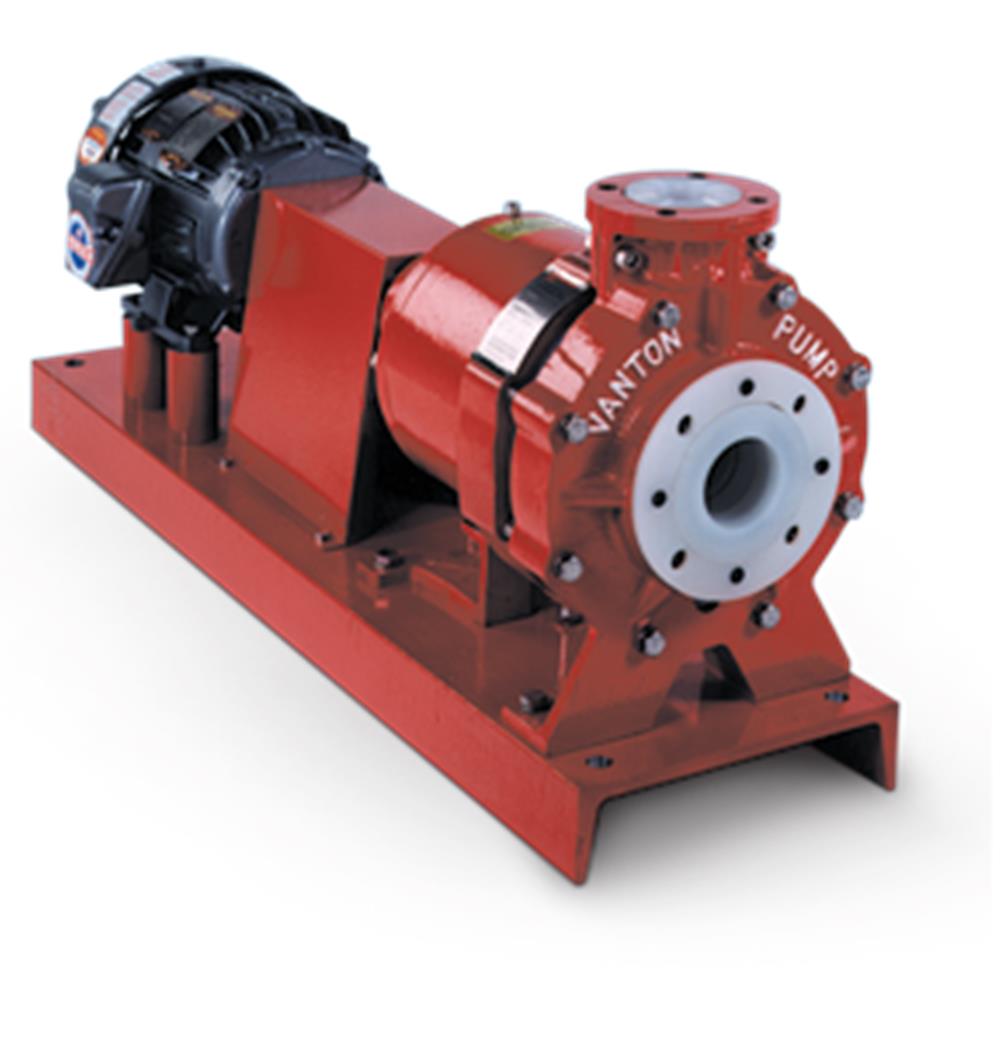
Vanton CHEM-GARD® CGM magnetically driven end suction process pumps are sealless, single stage, volute type centrifugals that conform to Hydraulic Institute Standards. All fluid contact parts are molded of solid polypropylene (PP) or polyvinylidene fluoride (PVDF), which are chemically inert and abrasion resistant. As a result CGM pumps eliminate corrosion associated with metal pumps, wicking and contamination associated with fiberglass pumps, and porosity/delamination associated with plastic lined metal pumps.
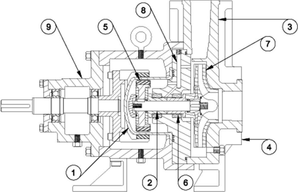
High performance, permanent, rare-earth magnets transmit power, with the inner magnet rotor assembly isolated from the pumped fluid by a thick-walled PP or PVDF encapsulation. A non-metallic containment can assembly reduces losses in magnetic force and pump efficiency by eliminating troublesome eddy currents.
With no seals to fail, and no metal contacting the fluid, these pumps are ideal for leak proof transfer of corrosive, toxic, hazardous and volatile liquids, and for handling of high purity water, reagent grade chemicals and other fluids that must remain contamination free.
CGM pumps can withstand the same nozzle loadings as metal pumps because the rugged thermoplastic wet end is supported by a protective structural metal armor.
Available with ANSI centerline suction and discharge, CGM pumps fit where conventionally sealed ANSI pumps were installed, without disturbing existing piping.
The wet end is comprised of solid, thick-sectioned, stand-alone components (unlike plastic linings), that are easily replaced, maximizing uptime while minimizing cost.
Features
- Dual non-metallic containment can assembly with a thermoplastic inner can to resist corrosive fluids, backed by a rigid non-metallic composite outer can. This construction avoids troublesome eddy currents and enhances efficiency.
- Thermoplastic sleeve assembly completely isolates the large diameter stainless steel shaft from the fluid.
- Pump casing, inner magnet bearing housing and impeller are molded from homogeneous, virgin thermoplastics (polypropylene or polyvinylidene fluoride). Metal armor provides structural protection and permits the pump to withstand the same nozzle loadings as metal pumps.
- External cast iron protective armor, which also serves to carry the nozzle loadings, is coated with a chemical resistant two-part epoxy paint to guard against chemical and atmospheric corrosion.
- High performance permanent rare-earth magnets offer power ratings to 30 hp at 3600 rpm for flow rates to 400 gpm (91 m3/h) at heads to 180 ft (55 m). The pumps are recommended for service at temperatures to 225°F (107°C).
- High PV stationary bearings and rotating sleeve/thrust bearings of silicon carbide are standard. Ultrapure alumina ceramic and other materials are available as options.
- Dynamically balanced, closed vane thermoplastic impellers with molded-in stainless steel inserts to assure rigidity, and are key locked to the shaft.
- Wide-open fluid passages provide for continuous flow of liquid for cooling and lubricating the sleeve/thrust bearings.
- Drive shaft bearing housing is furnished with heavy duty, sealed, grease-lubricated ball bearings.
The CGMC hydraulic head conforms to ANSI B73.1 process pump dimensional standards, allowing drop-in replacements without piping or installation modifications. Close-coupled design simplifies pump/motor alignment and reduces overall length by approximately 20% compared to conventionally mounted pumps, allowing placement in restricted spaces.
Every Vanton pump is fully tested to verify performance with all data permanently recorded.
CHEM-GARD® CGM PUMP DIMENSIONS: INCHES
Scroll table left and right for small devices.
| PUMP SIZE | ANSI DES. |
SUCTION SIZE |
DISCHARGE SIZE |
DIMENSIONS IN INCHES (MM) | ||||||
| CP | D | X | Y | HA* | HT | HB* | ||||
| 1.5 x 1 x 6 | AA | 1 1/2 | 1 | 17 1/2 | 5 1/4 | 6 1/2 | 4 | 12 | 3 1/2 | 39 |
| 3 x 2 x 6 | A-10 | 3 | 2 | 23 1/2 | 8 1/4 | 8 1/4 | 4 | 15 | 3 1/2 | 52 |
| 3 x 2 x 8 | A-60 | 3 | 2 | 23 1/2 | 8 1/4 | 9 1/2 | 4 | 15 | 3 1/2 | 52 |
| 4 x 3 x 8 | A-70 | 4 | 3 | 23 1/2 | 8 1/4 | 11 | 4 | 18 | 3 1/2 | 58 |
| 4 x 3 x 9 | A-70 | 4 | 3 | 23 1/2 | 8 1/4 | 11 | 4 | 18 | 3 1/2 | 58 |
| 4 x 3 x 10 | A-70 | 4 | 3 | 23 1/2 | 8 1/4 | 11 | 4 | 18 | 3 1/2 | 58 |
*Base plate dimensions will vary slightly with motor frame size.
All dimensions are approximate and not to be used for construction purposes.
Pump dimensions conform to ANSI B73.1.
Design specifics subject to modification as dictated by ongoing product improvement programs.


